Simplexity Projects
Below is a collection of some of the projects I have had the opportunity to work on while at Simplexity Product Development. The descriptions below are simplified and generalized to remove client sensitive details, and potential intellectual property has been removed.
Molecular Diagnostics R&D Tool Control PCB
Technical Skills Employed
- Electrical Engineering – PCB Schematic and Layout
- Fluidic/Pneumatic System Design
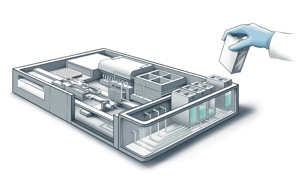
A client needed an R&D tool that performed various microfluidic, thermal, and motion operations as a Library Preparation Breadboard. Full details on the product are available on the Simplexity Website. The electronics were controlled through a PCB stack that had a STMicroelectronics Nucleo board as the main microcontroller to allow rapid development. I designed the schematics and layout for the main shield PCB to interface with electronic peripherals. Some notable interfaces on this shield were:
- Various Valve Drivers (inductive load) to employ Spike-and-Hold capabilities on valves
- An H-Bridge based motor driver
- 4-20 mA DAC and ADC for precision vacuum control
- Various optical/digital sensors
Additionally, I designed the system electrical schematics, cable designs, and contributed heavily to the fluidics, pneumatics, and vacuum design and routing.
Thermal Control Subsystem
Technical Skills Employed
- Mechanical Engineering
- Electrical Engineering
- Thermal Control Design
- Fluidic/Pneumatic System Design
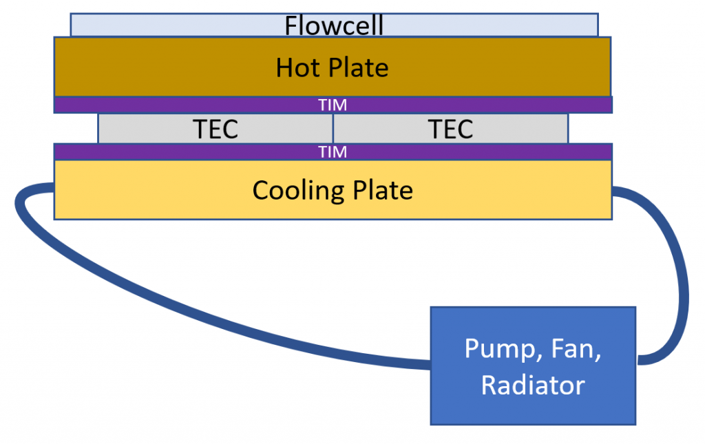
A molecular diagnostics client required precision temperature control of a flowcell inside a larger R&D tool. The application required rapid temperature changes, minimal temperature overshoot, high temperature precision, and high thermal uniformity across the flowcell, all while maintaining fluidic connections with the flowcell. I designed the TEC system that could achieve these goals including design of the mechanical parts and assembly, electrical system design, coolant system, and control hardware/tuning.
I discuss this project as well as some more technical background on Thermoelectric Coolers (TECs) in a previous blog post I wrote: Understanding Thermoelectric Coolers: Cooling Tech Simplified.
Satisfying the precision requirements took significant analysis and testing. I created a custom peltier element model and designed the thermal system using Modelica to get a preliminary idea of the thermal performance when ramping. Thermal resistance between the TECs and the plates was minimized by lapping the plate surfaces and testing various high performance thermal interface materials.
To speed up testing, I wrote a python script that interfaced directly with the thermal controller and measured temperature using external RTD sensors. This allowed verification testing to be accelerated, more repeatable, and autonomous.
AI Robotic Arm
Technical Skills Employed
- Mechanical Engineering
- Electrical Engineering
- Motion Control Design
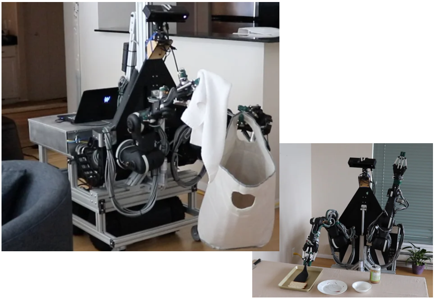
Aivot develops AI enhanced robotic solutions to intelligently automate labor. The robotic system consists of numerous sensors and electronics paired with robotic arms to learn to how to perform tasks from human demonstrations. A full case study of this project is available on the Simplexity Website, and I was responsible for designing the vertical lift mechanism, the electronics box wiring and cables, and performed the initial motion bring-up for an early prototype.
Due to the high number of electronics and actuators, this project required thorough design from the parent electrical architecture documentation down to the individual cable and E-Box wiring schematics. The cables and E-Box were specifically designed to reduce the electrical noise generated from the high motor currents while also allowing enough flexibility for the arms to achieve a large region of motion.
The motors also required individual bring up for each axis of motion. This entailed configuring the motor controller with proper safety limits, coupling the motor motion to magnetic encoders, and PID tuning to achieve desirable motion profiles under maximum load conditions.
Ceiling Mounted Asset Tracking Device
Technical Skills Employed
- Mechanical Engineering
- Thermal Analysis
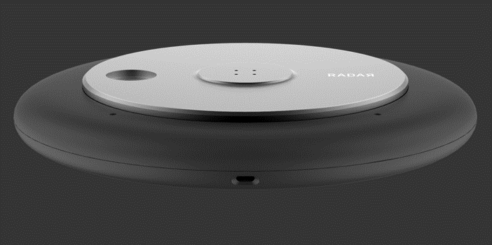
I designed the mechanical parts for an original prototype for Radar. Radar develops precision asset tracking systems using RFID and computer vision and needed a mechanical enclosure for ceiling-mounted electronics that were in development.
One of the principal challenges for this project was devising a method to exhaust the heat generated by the control boards in a sealed volume without using fans. To achieve this, the control boards were mounted using thermally conductive standoffs, thermal interface material, and a slight interference fit to ensure good thermal contact to the Aluminum Base plate. I then submitted multiple base plate designs for thermal simulation so we could further ensure that the heat would be exhausted in worst case conditions.
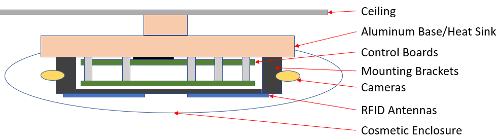
Additionally, there was a desire to reduce the COGS of the overall product. Some mounting brackets were designed as injection molded parts with common features to reduce part count while other mounting brackets were designed in sheet metal to reduce production costs. The Aluminum base was also designed so that it would be cheap to prototype using CNC machining, but the design could be easily modified at a later date when volumes demand the part to be die cast. The overall part count was reduced by merging distinct parts and cable routing features to simplify assembly/production.
I also designed the exterior of the enclosure so that it would be installable in a number of different environments, and the cosmetic cover was designed with a high degree of collaboration with an Industrial Design team.
Pogo Actuator
Technical Skills Employed
- Mechanical Engineering
- Motion System Design
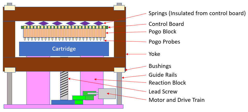
A Molecular Diagnostics client was developing a microfluidics cartridge, and I worked as a mechanical engineer to develop part of the instrument that forms an electrical interface with the cartridge. A simplified Front View of the “Pogo Subsystem” is shown below in the “Unclamped State”
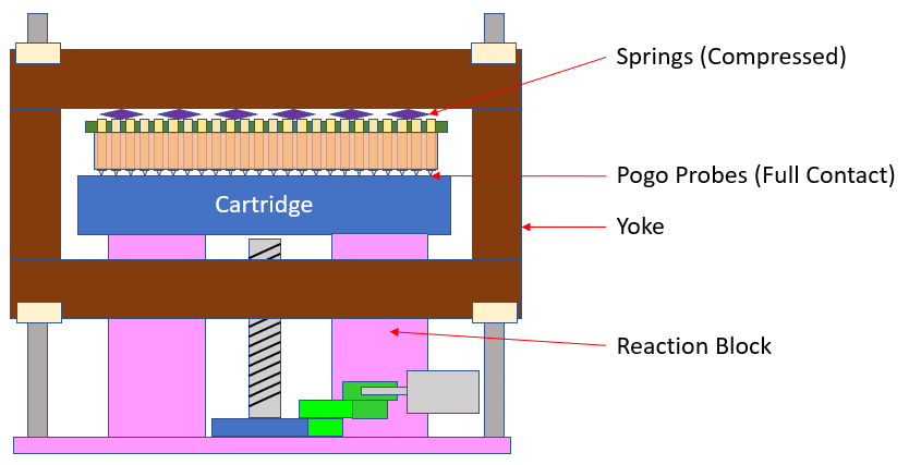
and the image below shows the “Clamped State”.
Due to severe space constraints, the Pogo Subsystem needed to be roughly 2D as depicted above. The workflow was:
- Load cartridge (into the screen) like a tape into a VHS player (Yes, I still remember those) so that it sits on the reaction block (pink).
- The instrument motor drives a series of cluster gears that then rotates a lead screw.
- The rotating lead screw pulls down the Yoke (brown) which compresses both the springs above the pogo block (purple) and the pogo probes against the cartridge.
- The control board (green) now has electrical contact to the cartridge via the pogo probes.
Design of this system faced a number of challenges. Firstly, due to the number of pogo probes needed, the output force of this subsystem needed to be on the order of 150-200 lbf to guarantee electrical contact. Don’t get your hand caught in there! This required Finite Element Analysis to verify the Yoke could support the forces without significant bowing. Additionally, there were initially challenges in getting the desired force without the motor stalling. A detailed load path analysis in the drive train highlighted unforeseen friction, and the issue was eventually resolved using a thrust bearing at the bottom surface of the lead screw.
Another aspect of the design was that the reaction block essentially set the cartridge reference plane or “datum” for other subsystems. As a result, the reaction block was designed to maintain a tight tolerance between the floor and reaction surface, and it also had other precision locating features that other subsystems could use.
Finally, the wide aspect ratio of the yoke was prone to binding, so careful consideration was needed so that it could slide over the guide rails with low friction and without over-defining the assembly. The chosen design path was to use custom designed hole and slot bushings that were pressed into the yoke and detailed assembly documentation to avoid over-defining the lead screw axis.
Personal Projects
Music Light Tower
Between 2015 and 2025 I had the opportunity to go to various music festivals with some friends. As many people use “totems” or light towers to help find each other in the crowds at these events, I eventually wanted to build one for myself.
In all cases below, the project focused on expanding my learnings, so all hardware was designed from scratch and made by hand i.e. custom designed PCBA (with many hours of hand soldering), electronics housings, light wiring, and tower design.
2023 – Fully Analog EL Lighting
For the first attempt at this light tower I wanted to challenge myself and make an Electroluminescent driver which outputs a roughly 100 V, 2 kHz signal to excite EL light cord.
Key specifications:
- 2 kHz signal generated using a phase shift oscillator
- 100 V rail generated using ZXSC410E6TA Boost Controller
- Analog design: high output impedance gain stage followed by low output impedance Class B amplifier
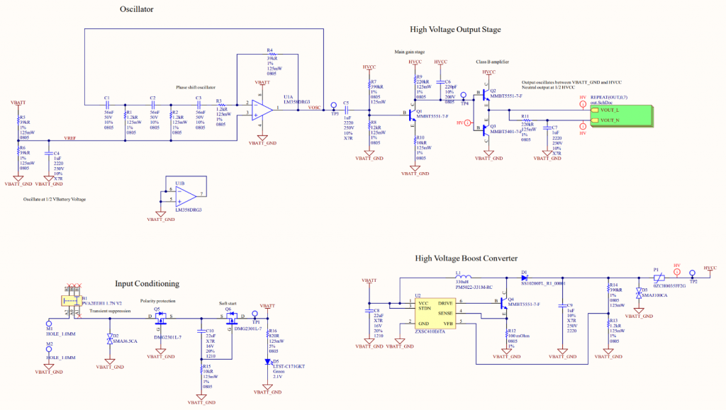
I simulated the circuit using LTSpice and designed the PCBA using Altium. Although the circuit worked on paper, I encountered a critical error after build: The BJT used at the boost controller required more current than the controller could provide. The quick fix was to use a spare MOSFET, but the voltage ceiling on that MOSFET turned out to be 50 V which turned out not to be enough to excite the EL wire.
This issue was not resolved in time to make it usable for any festivals, but the phase shift oscillator and amplifier stages worked as expected!
2024 – Introduce Sound Response
A bit disillusioned by the EL circuit but still aiming to avoid using an MCU, I transitioned the architecture to drive LEDs instead. Additionally, a new key goal was added: to adjust the light automatically to music Intensity.
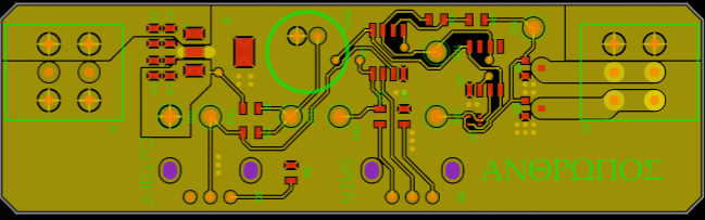
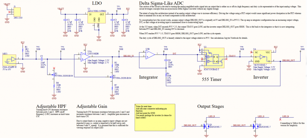
Key specifications:
- Adjustable HPF filter frequency and gain applied to microphone signal
- Uses Asynchronous Delta-Sigma-Like ADC design using integrator circuit, 555 Timer, and inverter.
- Drives LEDs in parallel, one color.
This design worked! However, when using this totem at the 2024 LIB festival, some notable annoyances were observed:
- The light would be very sensitive to strong transients (beats) and shine very brightly and quickly creating a strobing effect
- If the cutoff frequency was modified in either direction to try to reduce strobing, the light modulation effect became hard to see
2025 – The Real Deal (v3.0 and v3.1)
Emboldened by the previous totem but now hungry for more customizable features, I again shifted the architecture significantly. It finally felt like the right time to use a microcontroller.
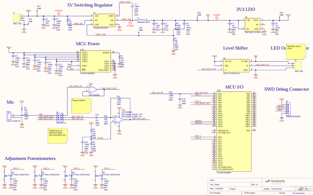
Key specifications:
- Light patterns using Addressable LEDs and custom timer design
- LED PCBA designed to allow 6 parallel channels of LEDs at top of tower
- 3D printed housing for Custom Controller PCBA
- 4 Knobs available for on-the-fly adjustments
I developed the firmware using a ST NUCLEO-F302R8 development board. This allowed me to test the LED driver code and various light setups before integrating the F302R8 MCU and committing to a custom PCBA. Although various addressable LED libraries exist, I did not find any that immediately worked for this MCU, so I decided to make my own LED driver by using one of the available MCU timers.
The firmware uses a simple four-state state machine that cycles through the following progression based on events triggered by hardware interrupts:
- Set timer and ADC to Mic Recording Mode
- Record Mic for a set time (roughly 60 kHz achieved).
- Process recorded mic data and calculate LED pattern. Prepare timer to write to LEDs.
- Write string to Addressable LEDs
Transients/beats were detected using a discrete time high pass filter (HPF) on the microphone signal. When a threshold was crossed, a pattern would be started so that white light would travel down from LED to LED starting at the top of the light tower.
An envelope filter was also used to generate a sound intensity signal. The intensity would then be used to drive the overall color-changing background brightness of the LEDs.
The electrical design is less interesting for this iteration as most of the design complexity was moved into the firmware. I added a HPF between the mic signal and the MCU ADC so that the signal was generally centered in the available range, and an RC anti-aliasing filter is present right at the ADC input, but otherwise all the remaining filtering and processing is done in discrete time.
A second board was also designed so that it could fan-out the LED signal into 6 parallel channels. This allowed the tower to achieve the effect that the lights are “raining” down from the top.
This design iteration was also the first to feature a custom mechanical housing for the PCBA. This helped hide/protect some of the exposed wiring and provided some marginal protection from the elements. This design was made in OnShape (new for me) and 3D printed using MJF with threaded inserts for cost effectiveness.
Shout out to Clint Smith who owned the mechanical tower design and build while I was drowning in troubleshooting!
Some brief videos that captured the final (until the next rev) device is shown below.
Although not (yet) well maintained, the files for this project are available on Github: https://github.com/neilfoxman/mic_totem/tree/main
The next iteration will target the following improvements:
- Use power, not just HPF signal to determine beat detection
- Improve granularity/sensitivity for intensity signal
neilfoxman · GitHub
Verious Github repos: A smattering of personal software projects at various degrees of completion.